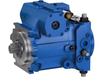
What are the key moving parts of an axial piston pump
An axial piston pump is a hydraulic pump that consists of multiple movable parts designed to pressurize and move hydraulic fluid. The key moving parts of an axial piston pump typically include:
1.Plungers: Axial piston pumps have multiple plungers that move axially (in and out) within their respective cylinders. These plungers are responsible for creating the pumping action by reciprocating back and forth as the pump rotates.
2. Cylinder or barrel: The plunger moves within a cylindrical hole or barrel in the cylinder. When the pump is running, the cylinder block rotates, causing the plunger to reciprocate.
3. Swash plate: The swash plate is a tilted or tilted plate that can be adjusted to control the angle of the plunger stroke. By changing the angle of the swash plate, the pump's displacement (the amount of hydraulic oil moved per revolution) can be adjusted.
4. Valve plate: The valve plate is the component that contains the hydraulic oil inlet and outlet. It helps control the flow of fluid in and out of the pump cylinder, ensuring hydraulic oil is pressurized and delivered to the system as needed.
5. Drive shaft: The drive shaft is connected to the prime mover (such as an electric motor or internal combustion engine) and is responsible for rotating the cylinder and other moving parts within the pump.
6. Bearings: Various types of bearings are used to support moving parts and reduce friction within the pump, ensuring the smooth operation and service life of the pump.
H1-P-130-R-B-A-A5-C2-N-D6-G-G3-H2-L-35-L-35-L-L-24-PN-NNN-NNN H1P130RBAA5C2ND6GG3H2L35L35LL24PNNNNNNN
H1-P-130-R-B-A-A5-C2-N-D6-G-G2-H6-L-42-L-42-L-L-24-PN-NNN-NNN H1P130RBAA5C2ND6GG2H6L42L42LL24PNNNNNNN
H1-P-130-R-B-A-A5-C2-N-D6-G-G2-H4-L-42-L-42-A-L-24-PN-NNN-NNN H1P130RBAA5C2ND6GG2H4L42L42AL24PNNNNNNN
H1-P-130-R-B-A-A5-C2-N-D6-G-G2-H4-L-30-L-30-L-L-24-PN-NNN-NNN H1P130RBAA5C2ND6GG2H4L30L30LL24PNNNNNNN
H1-P-130-R-B-A-A5-C2-N-D6-G-G2-H3-L-42-L-42-L-L-24-PN-NNN-NNN H1P130RBAA5C2ND6GG2H3L42L42LL24PNNNNNNN
H1-P-130-R-B-A-A5-C2-N-D6-G-G2-H3-L-33-L-33-L-L-24-PN-NNN-NNN H1P130RBAA5C2ND6GG2H3L33L33LL24PNNNNNNN
H1-P-130-R-B-A-A5-C2-N-D3-L-G3-H4-L-38-L-38-L-M-26-P4-NNN-NNN H1P130RBAA5C2ND3LG3H4L38L38LM26P4NNNNNN
H1-P-130-R-B-A-A5-C2-N-D3-L-G3-H3-L-38-L-38-L-M-26-P4-NNN-NNN H1P130RBAA5C2ND3LG3H3L38L38LM26P4NNNNNN
H1-P-130-R-B-A-A5-C2-N-D3-L-G3-H3-L-38-L-38-L-M-24-P4-NNN-NNN H1P130RBAA5C2ND3LG3H3L38L38LM24P4NNNNNN
H1-P-130-R-B-A-A5-C2-N-D3-L-G2-H6-L-42-L-42-L-M-26-P4-NNN-NNN H1P130RBAA5C2ND3LG2H6L42L42LM26P4NNNNNN
H1-P-130-R-B-A-A5-C2-N-D3-G-G3-H6-L-35-L-35-L-M-26-PN-NNN-NNN H1P130RBAA5C2ND3GG3H6L35L35LM26PNNNNNNN
H1-P-130-R-B-A-A5-C2-N-D3-G-G3-H6-L-35-L-35-L-M-24-PN-NNN-NNN H1P130RBAA5C2ND3GG3H6L35L35LM24PNNNNNNN
H1-P-130-R-B-A-A5-C2-N-D3-G-G3-H6-L-30-L-30-L-M-26-PN-NNN-NNN H1P130RBAA5C2ND3GG3H6L30L30LM26PNNNNNNN
H1-P-130-R-B-A-A5-C2-N-D3-G-G3-H3-L-42-L-42-A-N-28-PN-NNN-NNN H1P130RBAA5C2ND3GG3H3L42L42AN28PNNNNNNN
H1-P-130-R-B-A-A5-C2-N-D3-G-G3-H3-L-42-L-42-A-M-28-PN-NNN-NNN H1P130RBAA5C2ND3GG3H3L42L42AM28PNNNNNNN
H1-P-130-R-B-A-A5-C2-N-D3-G-G3-H3-L-42-L-42-A-M-24-PN-NNN-NNN H1P130RBAA5C2ND3GG3H3L42L42AM24PNNNNNNN
H1-P-130-R-B-A-A5-C2-N-D3-G-G3-H3-L-42-L-42-A-D-26-PN-NNN-NNN H1P130RBAA5C2ND3GG3H3L42L42AD26PNNNNNNN
H1-P-130-R-B-A-A5-C2-N-D3-G-G2-NN-L-35-L-35-A-M-24-PN-NNN-NNN H1P130RBAA5C2ND3GG2NNL35L35AM24PNNNNNNN
H1-P-130-R-B-A-A5-C2-N-D3-G-G2-NN-L-23-L-23-A-M-24-PN-NNN-NNN H1P130RBAA5C2ND3GG2NNL23L23AM24PNNNNNNN
H1-P-130-R-B-A-A5-C2-N-D3-G-G2-H6-L-42-L-42-L-M-24-PN-NNN-NNN H1P130RBAA5C2ND3GG2H6L42L42LM24PNNNNNNN
7. Seals and gaskets: used to prevent hydraulic oil leakage and maintain the necessary pressure in the pump.
8. Casing or casing: The casing or casing of a pump encloses and protects its internal components.
9. Inlet and outlet: The pump has specific inlets and outlets connected to the hydraulic system. Hydraulic oil is drawn into the pump through the inlet and pressurized, and then delivered to the system through the outlet.
10. Manifold: The manifold is a component that connects the inlet and outlet of the pump with the valve plate and controls the flow of hydraulic oil. It can be a separate component or integrated into the housing or valve plate.
11. Variable displacement control: Axial piston pumps have fixed displacement and variable displacement designs. Fixed displacement pumps have a constant output flow, while variable displacement pumps allow the operator to adjust the flow rate by changing the swashplate angle or through other control mechanisms. Variable displacement pumps are particularly useful in applications that require varying flow and pressure.

12. Efficiency: Axial piston pumps are known for their high efficiency, especially in variable displacement configurations. By adjusting the swashplate angle to suit system needs, these pumps can operate at optimal levels, reducing energy consumption and heat generation.
13. Multi-cylinder configuration: Axial piston pumps can have different cylinder configurations, such as in-line, bent-axis or multi-head bent-axis. Each configuration has specific advantages and can be selected based on the requirements of the hydraulic system.
14. Noise and vibration: The reciprocating motion of the plunger in an axial piston pump will produce noise and vibration. To alleviate this, many pumps are noise-reducing and are often mounted on a vibration-absorbing surface.
15. Regular maintenance: In order to ensure the service life and reliability of the axial piston pump, regular maintenance is very important, including checking and replacing seals, gaskets and lubrication, as well as monitoring the wear of moving parts.
16. Application diversity: Axial piston pumps are used in a wide range of applications, from construction and agricultural equipment to industrial machinery, aircraft and automotive systems. Their adaptability and ability to provide precise hydraulic control make them a popular choice across a variety of industries.
H1-P-130-R-B-A-A5-C2-N-D3-G-G2-H6-L-42-L-42-A-M-28-PN-NNN-NNN H1P130RBAA5C2ND3GG2H6L42L42AM28PNNNNNNN
H1-P-130-R-B-A-A5-C2-N-D3-G-G2-H6-L-35-L-35-A-M-24-PN-NNN-NNN H1P130RBAA5C2ND3GG2H6L35L35AM24PNNNNNNN
H1-P-130-R-B-A-A5-C2-N-D3-G-G2-H5-L-23-L-23-A-M-24-PN-NNN-NNN H1P130RBAA5C2ND3GG2H5L23L23AM24PNNNNNNN
H1-P-130-R-B-A-A5-C2-N-D3-G-G2-H4-L-42-L-42-A-M-24-PN-NNN-NNN H1P130RBAA5C2ND3GG2H4L42L42AM24PNNNNNNN
H1-P-130-R-B-A-A5-C2-N-D3-G-G2-H3-L-42-L-42-A-M-26-PN-NNN-NNN H1P130RBAA5C2ND3GG2H3L42L42AM26PNNNNNNN
H1-P-130-R-B-A-A5-C2-N-D3-G-G2-H1-L-42-L-42-A-M-24-PN-NNN-NNN H1P130RBAA5C2ND3GG2H1L42L42AM24PNNNNNNN
H1-P-130-R-B-A-A5-C2-N-D3-G-G2-E5-L-30-L-30-L-M-24-PN-NNN-NNN H1P130RBAA5C2ND3GG2E5L30L30LM24PNNNNNNN
H1-P-130-R-B-A-A5-C2-N-D3-G-F3-NN-L-30-L-30-A-M-24-PN-NNN-NNN H1P130RBAA5C2ND3GF3NNL30L30AM24PNNNNNNN
H1-P-130-R-B-A-A5-C2-N-D3-G-F3-H6-L-30-L-30-A-N-24-PN-NNN-NNN H1P130RBAA5C2ND3GF3H6L30L30AN24PNNNNNNN
H1-P-130-R-B-A-A5-C2-N-D3-G-F3-H6-L-30-L-30-A-M-20-PN-NNN-NNN H1P130RBAA5C2ND3GF3H6L30L30AM20PNNNNNNN
H1-P-130-R-B-A-A5-C2-N-D3-G-F3-H2-L-42-L-42-L-M-26-PN-NNN-NNN H1P130RBAA5C2ND3GF3H2L42L42LM26PNNNNNNN
H1-P-130-R-B-A-A5-C2-B-D8-G-G3-NN-L-30-L-30-A-P-24-PN-NNN-NNN H1P130RBAA5C2BD8GG3NNL30L30AP24PNNNNNNN
H1-P-130-R-B-A-A5-C2-B-D8-G-G2-NN-L-38-L-20-A-P-20-PN-NNN-NNN H1P130RBAA5C2BD8GG2NNL38L20AP20PNNNNNNN
H1-P-130-R-B-A-A5-C2-B-D8-G-G2-NN-L-35-L-35-A-P-20-PN-NNN-NNN H1P130RBAA5C2BD8GG2NNL35L35AP20PNNNNNNN
H1-P-130-R-B-A-A5-C2-B-D8-G-G2-NN-L-35-L-20-L-P-20-PN-NNN-NNN H1P130RBAA5C2BD8GG2NNL35L20LP20PNNNNNNN
H1-P-130-R-B-A-A5-C2-B-D8-G-G2-NN-L-35-L-20-A-P-20-PN-NNN-NNN H1P130RBAA5C2BD8GG2NNL35L20AP20PNNNNNNN
H1-P-130-R-B-A-A5-C2-B-D8-G-G2-H4-L-30-L-30-A-P-24-PN-NNN-NNN H1P130RBAA5C2BD8GG2H4L30L30AP24PNNNNNNN
H1-P-130-R-B-A-A5-C2-B-D6-G-G2-H6-L-35-L-35-L-L-24-PN-NNN-NNN H1P130RBAA5C2BD6GG2H6L35L35LL24PNNNNNNN
H1-P-130-R-B-A-A5-C2-B-D6-G-G2-H3-L-45-L-45-L-L-24-PN-NNN-NNN H1P130RBAA5C2BD6GG2H3L45L45LL24PNNNNNNN
H1-P-130-R-B-A-A5-C2-B-D6-G-G2-H3-L-33-L-33-L-L-24-PN-NNN-NNN H1P130RBAA5C2BD6GG2H3L33L33LL24PNNNNNNN
The operation of an axial piston pump consists of the following steps:
1. Rotation: When the transmission shaft rotates, it drives the cylinder to rotate accordingly.
2. Reciprocating motion: The plungers in the cylinder reciprocate back and forth in their respective cylinders due to the action of the swash plate. As the cylinder block rotates, the plunger is pushed in and out of the cylinder.
3. Suction and discharge: When the plunger moves outward, a low-pressure area is formed in its cylinder, causing hydraulic oil to be sucked in through the inlet and fill the cylinder. As the plunger moves inward, it pressurizes the hydraulic fluid, pushing it out of the outlet.
4. Pressure adjustment: The angle of the swash plate can be adjusted to control the stroke of the plunger, thereby controlling the displacement and pressure of the pump. This feature allows variable flow and pressure control to meet the specific requirements of the hydraulic system.
5. Seals and Lubrication: Seals and gaskets are essential to prevent leaks and ensure a tight seal between moving parts, while lubrication is essential to reduce friction and wear within the pump.
It is important to note that axial piston pumps come in different designs and variations, such as swashplate designs and cylinder configurations, which may affect the specific operation and characteristics of a given pump. Engineers and operators select the appropriate axial piston pump based on the requirements of the hydraulic system, taking into account factors such as flow, pressure and control options.
This article is published by the official website of Baolilai Hydraulics, please contact the author and indicate the source for reprinting:https://www.baolilai-pump.cn/news/1151.html


