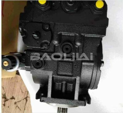
The key role of hydraulic pump outlet damping and its optimization method
Damping at the outlet of a hydraulic pump does affect the operation of the hydraulic system. Outlet damping (often called flow control or pressure control) is critical for the following reasons:
1. Flow control: Damping controls the flow of hydraulic oil leaving the pump. It ensures that the hydraulic system receives consistent and controlled flow, preventing sudden surges or drops in flow. This is critical to maintaining system stability and efficiency.
2. Pressure control: Outlet damping can help regulate the pressure within the hydraulic system. It prevents excessive pressure spikes that can damage components and compromise system safety. Pressure control is critical to the proper operation of hydraulic actuators and other components.
3. System stability: Proper damping can help maintain system stability by preventing rapid changes in flow and pressure. This stability is critical for precise control of hydraulic actuators, such as cylinders and motors, and for consistent and predictable system performance.
4. Energy efficiency: Damping can improve energy efficiency by reducing pressure losses and optimizing flow paths. This helps minimize energy consumption and improve the overall efficiency of the hydraulic system.
5. Component Protection: Damping protects hydraulic components such as valves, cylinders and motors from the damaging effects of pressure transients and sudden flow changes. This extends component life and reduces maintenance costs.
6. Control accuracy: For applications requiring precise control, outlet damping plays a vital role. It ensures that the hydraulic system responds accurately to input signals and maintains required performance levels.
H1-P-165-R-C-A-P9-C2-D-D6-L-G2-H6-L-40-L-40-L-L-26-P2-NNN-D6F H1P165RCAP9C2DD6LG2H6L40L40LL26P2NNND6F
H1-P-165-R-C-A-N2-C2-D-D5-G-G2-H4-L-45-L-45-L-M-28-P1-NNN-NNN H1P165RCAN2C2DD5GG2H4L45L45LM28P1NNNNNN
H1-P-165-R-C-A-N2-C2-C-D6-G-G2-H3-L-38-L-38-L-L-26-P1-NNN-NNN H1P165RCAN2C2CD6GG2H3L38L38LL26P1NNNNNN
H1-P-165-R-C-A-N1-C3-C-D6-G-G2-H2-K-33-K-33-L-L-28-P1-NNN-NNN H1P165RCAN1C3CD6GG2H2K33K33LL28P1NNNNNN
H1-P-165-R-C-A-M6-C7-B-D6-G-G3-H5-L-45-L-45-L-L-22-H1-NNN-M00 H1P165RCAM6C7BD6GG3H5L45L45LL22H1NNNM00
H1-P-165-R-C-A-M5-C2-B-D6-G-G3-NN-L-28-L-28-L-L-24-PN-NNN-NNN H1P165RCAM5C2BD6GG3NNL28L28LL24PNNNNNNN
H1-P-165-R-C-A-M2-C2-B-D3-G-G2-H2-L-38-L-38-L-M-24-H1-NNN-M00 H1P165RCAM2C2BD3GG2H2L38L38LM24H1NNNM00
H1-P-165-R-C-A-M1-C7-B-D3-G-G2-H6-L-25-L-25-L-M-24-H1-NNN-M00 H1P165RCAM1C7BD3GG2H6L25L25LM24H1NNNM00
H1-P-165-R-C-A-M1-C7-B-D3-G-G2-H2-L-25-L-25-L-M-24-H1-NNN-M00 H1P165RCAM1C7BD3GG2H2L25L25LM24H1NNNM00
H1-P-165-R-C-A-M1-C4-B-D9-G-G2-H4-L-30-L-30-L-L-24-H1-NNN-M00 H1P165RCAM1C4BD9GG2H4L30L30LL24H1NNNM00
H1-P-165-R-C-A-M1-C4-B-D6-G-G3-H2-L-30-L-30-L-L-24-H1-NNN-M00 H1P165RCAM1C4BD6GG3H2L30L30LL24H1NNNM00
H1-P-165-R-C-A-E8-C2-N-D9-G-G2-H4-L-38-L-20-L-L-24-PN-NNN-NNN H1P165RCAE8C2ND9GG2H4L38L20LL24PNNNNNNN
H1-P-165-R-C-A-E8-C2-N-D8-G-G2-H6-K-30-K-30-A-P-24-PN-NNN-NNN H1P165RCAE8C2ND8GG2H6K30K30AP24PNNNNNNN
H1-P-165-R-C-A-E8-C2-N-D7-G-G2-H4-L-38-L-38-N-E-24-PN-NNN-NNN H1P165RCAE8C2ND7GG2H4L38L38NE24PNNNNNNN
H1-P-165-R-C-A-E8-C2-N-D6-G-G3-H6-L-38-L-20-L-L-24-PN-NNN-NNN H1P165RCAE8C2ND6GG3H6L38L20LL24PNNNNNNN
H1-P-165-R-C-A-E8-C2-N-D3-G-G2-H1-L-40-L-40-L-M-24-PN-NNN-NNN H1P165RCAE8C2ND3GG2H1L40L40LM24PNNNNNNN
H1-P-165-R-C-A-E7-C2-N-D8-G-G3-NN-L-45-L-45-L-P-26-PN-NNN-NNN H1P165RCAE7C2ND8GG3NNL45L45LP26PNNNNNNN
H1-P-165-R-C-A-E7-C2-N-D8-G-G3-NN-L-40-L-40-L-P-26-PN-NNN-NNN H1P165RCAE7C2ND8GG3NNL40L40LP26PNNNNNNN
H1-P-165-R-C-A-E7-C2-N-D6-G-G3-H3-L-38-L-38-L-L-24-PN-NNN-NNN H1P165RCAE7C2ND6GG3H3L38L38LL24PNNNNNNN
H1-P-165-R-C-A-A9-C1-N-D8-G-F3-H5-L-30-L-20-L-P-26-PN-NNN-NNN H1P165RCAA9C1ND8GF3H5L30L20LP26PNNNNNNN
Some common components used for outlet damping in hydraulic systems:
1. Pressure relief valve: Pressure relief valves are designed to limit the maximum pressure in a hydraulic system. When the pressure exceeds a preset value, these valves open, allowing excess liquid to return to the reservoir. This prevents pressure spikes and protects the system from overpressure, which can otherwise damage components. Pressure relief valves are critical to safety and protecting systems from catastrophic failure.
2. Flow control valve: The flow control valve is used to regulate the flow of fluid leaving the pump. By managing flow, these valves can be adjusted to control the speed of a hydraulic actuator, such as a cylinder. Flow control valves are critical for achieving precise control in applications where speed of movement is critical.
3. Accumulator: An accumulator is a hydraulic device that stores energy in the form of pressurized fluid. They serve as both energy sources and damping components. Accumulators help dampen pressure peaks, reduce flow fluctuations and provide auxiliary power during peak demand periods. They are particularly useful in applications where smooth and consistent operation is critical.

4. Proportional valve: Proportional valves are advanced control valves that can adjust flow and pressure in real time, usually in response to electronic control signals. They are used in applications requiring precise and variable control of hydraulic parameters. These valves provide a high degree of control and help improve the accuracy of hydraulic systems.
5. Prevent cavitation: Damping can also prevent cavitation, which is the formation of steam-filled cavities in the hydraulic oil due to low pressure. Cavitation can damage pumps and other hydraulic components. A properly designed damping system helps maintain adequate pressure levels and avoid cavitation.
6. Load characteristics: The type of load driven by the hydraulic system can significantly affect damping requirements. For example, loads that change position or speed rapidly may require more complex damping solutions to ensure smooth and precise control.
7. Tuning and Optimization: Damping components and control settings often require fine-tuning to match specific operating requirements. This process may involve adjusting flow controls or pressure relief valves to optimize system performance for a given application.
H1-P-165-R-C-A-A9-C1-B-D3-G-G3-NN-L-38-L-38-L-M-26-PN-NNN-NNN H1P165RCAA9C1BD3GG3NNL38L38LM26PNNNNNNN
H1-P-165-R-C-A-A5-C3-N-D8-G-G2-H3-L-33-L-33-L-P-24-PN-NNN-NNN H1P165RCAA5C3ND8GG2H3L33L33LP24PNNNNNNN
H1-P-165-R-C-A-A5-C3-N-D3-G-G3-NN-L-35-L-35-L-M-28-PN-NNN-NNN H1P165RCAA5C3ND3GG3NNL35L35LM28PNNNNNNN
H1-P-165-R-C-A-A5-C3-N-D3-G-G3-NN-L-35-L-35-A-M-24-PN-NNN-NNN H1P165RCAA5C3ND3GG3NNL35L35AM24PNNNNNNN
H1-P-165-R-C-A-A5-C3-N-D3-G-G3-H6-L-42-L-42-L-M-26-PN-NNN-NNN H1P165RCAA5C3ND3GG3H6L42L42LM26PNNNNNNN
H1-P-165-R-C-A-A5-C3-N-D3-G-G3-H6-L-35-L-35-A-M-24-PN-NNN-NNN H1P165RCAA5C3ND3GG3H6L35L35AM24PNNNNNNN
H1-P-165-R-C-A-A5-C3-B-D9-G-G3-H4-L-42-L-42-L-L-28-PN-NNN-NNN H1P165RCAA5C3BD9GG3H4L42L42LL28PNNNNNNN
H1-P-165-R-C-A-A5-C3-B-D9-G-G3-H4-K-25-K-25-A-L-24-PN-NNN-NNN H1P165RCAA5C3BD9GG3H4K25K25AL24PNNNNNNN
H1-P-165-R-C-A-A5-C3-B-D9-G-G2-H4-L-42-L-42-L-L-28-PN-NNN-NNN H1P165RCAA5C3BD9GG2H4L42L42LL28PNNNNNNN
H1-P-165-R-C-A-A5-C3-B-D6-G-G3-NN-L-25-L-25-A-L-24-PN-NNN-NNN H1P165RCAA5C3BD6GG3NNL25L25AL24PNNNNNNN
H1-P-165-R-C-A-A5-C3-B-D6-G-G3-NN-K-25-K-25-A-L-24-PN-NNN-NNN H1P165RCAA5C3BD6GG3NNK25K25AL24PNNNNNNN
H1-P-165-R-C-A-A5-C3-B-D6-G-G3-H6-L-42-L-42-L-L-28-PN-NNN-NNN H1P165RCAA5C3BD6GG3H6L42L42LL28PNNNNNNN
H1-P-165-R-C-A-A5-C3-B-D6-G-G3-H3-L-42-L-42-L-L-28-PN-NNN-NNN H1P165RCAA5C3BD6GG3H3L42L42LL28PNNNNNNN
H1-P-165-R-C-A-A5-C3-B-D6-G-G2-H6-L-42-L-42-L-L-28-PN-NNN-NNN H1P165RCAA5C3BD6GG2H6L42L42LL28PNNNNNNN
H1-P-165-R-C-A-A5-C3-B-D3-G-G3-NN-L-35-L-35-A-M-24-PN-NNN-NNN H1P165RCAA5C3BD3GG3NNL35L35AM24PNNNNNNN
H1-P-165-R-C-A-A5-C3-B-D3-G-G3-H6-L-35-L-35-A-M-24-PN-NNN-NNN H1P165RCAA5C3BD3GG3H6L35L35AM24PNNNNNNN
H1-P-165-R-C-A-A5-C3-B-D3-G-G3-H6-K-40-K-20-L-M-24-PN-NNN-NNN H1P165RCAA5C3BD3GG3H6K40K20LM24PNNNNNNN
H1-P-165-R-C-A-A5-C3-B-D3-G-G3-H3-L-35-L-35-A-M-24-PN-NNN-NNN H1P165RCAA5C3BD3GG3H3L35L35AM24PNNNNNNN
H1-P-165-R-C-A-A5-C3-B-D3-G-G2-H6-L-30-L-30-L-M-24-PN-NNN-NNN H1P165RCAA5C3BD3GG2H6L30L30LM24PNNNNNNN
H1-P-165-R-C-A-A5-C2-N-D9-G-G2-H4-L-42-L-42-L-L-24-PN-NNN-NNN H1P165RCAA5C2ND9GG2H4L42L42LL24PNNNNNNN
8. System response time: The response time of a hydraulic system is critical, especially in applications that require rapid adjustment. Damping components and control strategies should be designed to achieve the required response time without overshoot or instability.
9. System layout and piping: Proper design of hydraulic system layout and piping is critical for effective damping. Avoiding sharp bends, restrictions and dead-end pockets in pipes helps maintain the integrity of the damping process and reduce pressure losses.
10. Maintenance and Monitoring: Regular maintenance and monitoring of damping components is essential to ensure their continued effectiveness. Regular inspections and testing can detect issues such as valve wear, clogs, or leaks that may affect system performance.
11. Environmental considerations: In some applications, environmental factors such as temperature and fluid contamination may affect the performance of damping components. Selection and maintenance should take these factors into consideration.
12. Hydraulic oil characteristics: Hydraulic oil characteristics (including viscosity and temperature) affect damping. Changes in fluid characteristics may require adjustments to damping components or control settings.
In summary, outlet damping is a critical aspect of hydraulic system design and operation that involves a variety of components and considerations to ensure safe, efficient, and precise system operation. The selection, configuration, and ongoing maintenance of damping components are critical to meeting the specific requirements of a given hydraulic application. Engineers and operators must carefully evaluate these factors to achieve the required performance and reliability of hydraulic systems.
This article is published by the official website of Baolilai Hydraulics, please contact the author and indicate the source for reprinting:https://www.baolilai-pump.cn/news/1145.html


