ERL130BBS3120NNN3S4APA1NAAANNNNNN piston pump
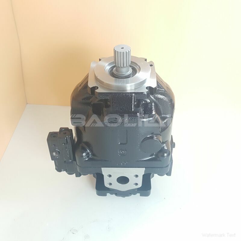
ERL130BBS3120NNN3S4APA1NAAANNNNNN piston pump
- Product Details
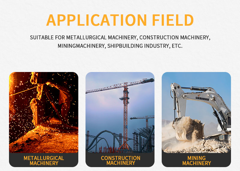
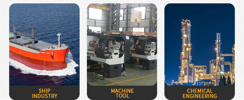
- Applicable Scene
Hydraulic gear pumps are essential components in various industrial applications, providing a reliable means of transferring hydraulic fluid from one location to another. Understanding their working principle is crucial for anyone involved in hydraulic systems, whether in machinery, automotive, or manufacturing processes. This article will explore how hydraulic gear pumps function, their advantages, and common applications.
ER-L-130B-BS-31-20-NN-N-3-S4AP-A1N-AAA-NNN-NNN
ERL130BBS3120NNN3S4APA1NAAANNNNNN
At its core, a hydraulic gear pump consists of a pair of gears housed within a casing. The primary function of these gears is to create a pressure differential that draws hydraulic fluid into the pump and forces it out under pressure. The operation can be broken down into several key phases:
83047159
Intake Phase: As the gears rotate, one gear moves down while the other moves up, creating a space that expands on one side of the pump. This expansion reduces pressure, drawing hydraulic fluid from the reservoir into the pump through an inlet port. The design ensures that the gears mesh tightly, minimizing the possibility of fluid leaking back into the reservoir.
Transfer Phase: Once the gears are full of hydraulic fluid, their rotation continues. The meshing of the gears traps the fluid between them and the casing, transporting it around the outside of the pump. As the gears turn, they push this fluid toward the discharge port, creating a continuous flow.
Discharge Phase: When the gears finish their rotation, they reach the discharge side, and the volume they have transported is forced out under pressure. The continuous rotation of the gears ensures a constant flow of hydraulic fluid, which is essential for the operation of hydraulic systems.